


 Improperly sealed cable penetrations are a serious problem. There are three facts of life when it comes to firestopping and smoke sealing data and communications cable penetrations…
1. Change is constant.
2. Cable bundles are inherently leaky.
3. Conventional cable firestopping requires human beings to do the job right every time!
These factors combine to make cable penetrations the weak link in fire-protection in virtually every cable-intensive facility.
The EZ-Path® System was developed to solve this problem. This product represents a break through in the protection of cable-intensive facilities. EZ-Path means no firestopping or smoke sealing ever! All the while allowing complete access to cabling for easy moves, adds, and changes! Is it too good to be true? You be the judge. First you will need to understand the issues regarding cables and smoke. There is a great deal of misinformation out there regarding this topic. You will also need a better understanding of code requirements. Our intent here is to provide you with the information needed to make an intelligent choice regarding cable firestopping protection.
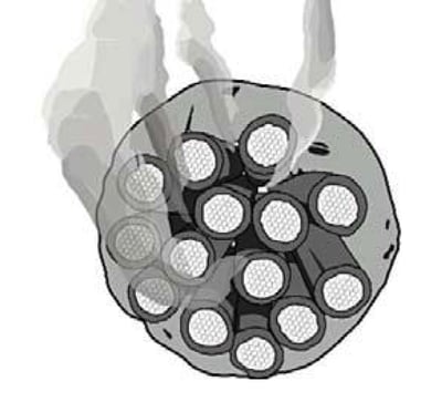
Cable bundles are inherently leaky! Surprised? Looking at a cable bundle in a sleeve with putty packed around it, most people just naturally assume that the seal is virtually hermetic. But in reality if there is a fire, there will be smoke transmission. It’s really just a question of how much (See Fig. 1). Let’s discuss cable leakage. Why and how it occurs, and how EZ-Path can help you deal with it without having to completely give up on making cable changes.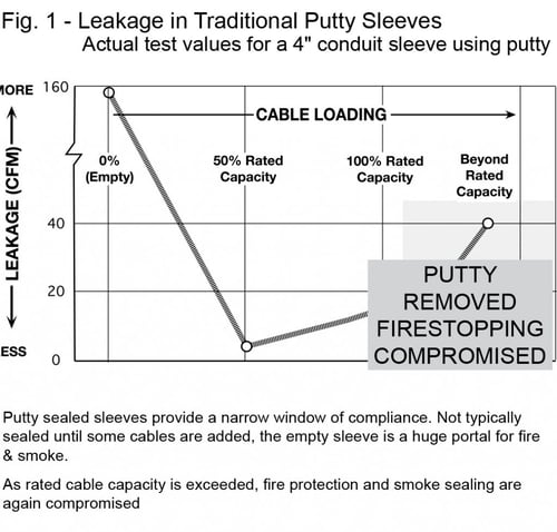
There are situations where cable bundles must be tightly sealed. For example in marine applications where cables are installed in areas that are below the water line, water and airtight sealing is a logical requirement. In these applications, devices called cable transit systems using rubber plugs are fitted into steel frames welded into the bulkheads. These rubber plugs are sized to fit each individual cable and actually squeeze them for a tight seal. Above the water line, water and air tight sealing is not generally required and is considered to be impractical.
Normal buildings are not intended to be completely airtight. Some air flow is actually essential. Buildings constructed too tightly are frequently cited as the cause of a malady known as Sick Building Syndrome.
Even fire doors are not designed to be perfectly airtight. The same holds true for fire and smoke dampers which in many cases are actually required to be loosely fitted within their openings are not typically externally gasketed or sealed. With few exceptions, the codes not only do not mandate tight seals but actually permit a certain percentage of unsealed openings.
Why are cable bundles leaky? The short answer is that there is significant unsealed space between the cables within the bundle. In the typical cable/sleeve penetration after the sleeve is installed, some amount of cables will be added before any firestopping is performed. At this point not only is the sleeve completely open to the passage of smoke but it is also a pathway for fire itself. Once some cables are installed, firestop sealant, putty, or foam muffins may be installed around the cable bundle. The keyword here is around. Firestopping will not typically be installed within the cable bundle.
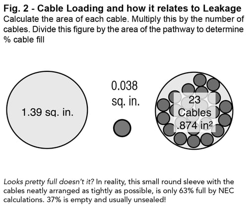 Another factor that contributes to this problem is the fact that round cables do not load very efficiently into round sleeves. Fig. 2 illustrates this problem. Anywhere from 35% to 50% of the space occupied by the cable bundles may be unsealed interstitial space. Firestopping requires additional space. Thus the actual cable loading may be reduced even further.
The effectiveness of traditional cable sleeve firestopping methods can’t be quantified. By code, through penetrations fall into a category referred to as unprotected openings. The codes place limits on the amount of unsealed space there may be in floors and walls. In theory, unprotected openings must be considered in this equation. This is expressed as Total Leakage Area. By rights, all cable penetrations should be considered in this calculation. The question becomes…How would you do it?
Considering that there often is no rhyme or reason as to the size or number of sleeves used. No one ever knows exactly how many cables are installed in each sleeve or just what the percentage fill might be… Not to mention the fact that no one really knows how effective the seal may be (assuming the firestop is still there). How could you possibly figure this out? The simple answer is that you can’t.
Reliability? Firestop systems, products, or methods that require you to remove and reinstall firestopping, or mechanically adjust the firestop device in order to add or remove cables simply are not reliable. It doesn’t matter whether you are using putty, sealant, or foam muffins.
Careful installation the first time around might reduce your potential for leakage, but the same care must be exercised in reinstalling the seal after every change. What are the chances that this will occur? An additional problem with these traditional systems is that they provide no fail safe method for assuring that allowable loading will not be exceeded. Too many cables equate to too little firestopping, along with excessive leakage.
Published L Ratings – Be Sure to Read the Small Print!
Extremely low numbers for cables usually mean that each cable has been individually sealed. Is this practical? Some pathway devices with self-contained firestopping require putty to be packed in both ends in order to achieve the rating. Be sure to read the small print. For more information regarding the L Rating, see STI Technical Update entitled The Problem with Leakage Ratings.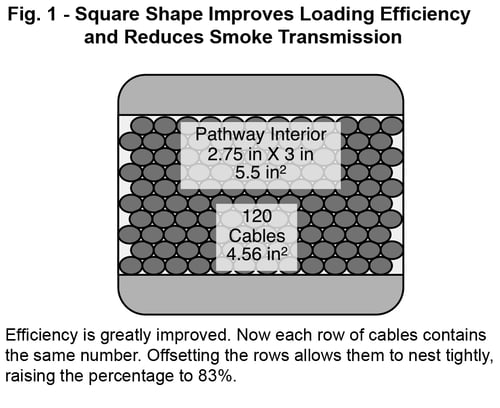
The EZ-Path® System Simply a better solution! Back in late 2002, the EZ-Path® Cable Penetration System was introduced. EZ-Path® garnered a great deal of attention from IT managers, RCDD/Specifiers, as well as cable installers. EZ-Path® promised to solve cable penetration problems for good by providing fail-safe protection against the propagation of fire and smoke. Let’s see how well EZ-Path® delivers on that promise…
EZ-Path’s® self-contained firestopping design has proven itself time and again in UL fire testing, providing outstanding fire and thermal performance. EZ-Path® is billed as providing complete protection whether empty as installed, or completely filled until no more cables can be added, or any where in between.
EZ-Path® has demonstrated consistently excellent smoke sealing results. In extensive testing conducted by Underwriters Laboratories, Inc., EZ-Path® has produced results, comparable to or even better in fact, than carefully installed putty systems (See Fig. 3). Unlike other sleeve products with integrated firestopping that optionally use
putty or sealant to provide leakage values, EZ-Path® accomplishes the sealing task with no supplemental products or additional efforts required.
The EZ-Path® has a square shape which means far greater cable loading efficiency and lower smoke transmission. We discussed earlier the fact that round cables and round pathways when it comes to effective cable loading. EZ-Path® is square and that in itself is an improvement. Depending on the size of the cable, EZ-Path® can provide a cross sectional loading efficiency of up to 85% (compared to 50 to 65% for round sleeves). What accounts for the improvement? The square shape allows cables to nest better than the round shape (See Fig. 1). But just being square is not the complete secret to its success.
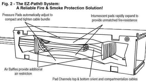 The EZ-Path® patented design automatically adjusts to the cable bundle size and profile. This design has been refined with subtle improvements since its introduction that
have taken a great product and made it even better. Resilient Intumescent foam pads form inward facing arches that meet in the center of the pathway. As cables are inserted, the pads are displaced upward and downward to accommodate the changed cable profile. The pads are segmented to allow for more precise adjustment and tighter sealing. The pads provide a very gentle squeezing action that assists in orienting the cables. In addition to the pads, air baffles installed at each end of the pathway further restrict air flow.
EZ-Path® makes code compliance easier! How so you may ask? EZ-Path® not only provides excellent leakage values but it also provides something that no other product does and no traditional solution can do and that is provide published values for Total Leakage Area. Using this value, it is possible to predict the maximum leakage area represented by the cable penetrations merely by counting the number of pathways installed.
When it comes to cable penetrations, the EZ-Path® System represents the highest level of consistent fire and smoke protection available today. No other product provides automatic firestopping and smoke sealing without the need to remove, replace, trim, or adjust materials or parts.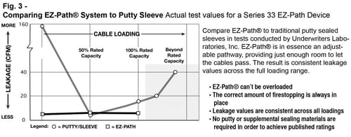
The EZ-Path® System also eliminates the potential for human errors. Even the best intention people can and do make mistakes. We constantly see facilities with improperly sealed openings and even openings that are completely unsealed. With the automatic protection that EZ-Path® provides, the potential for this happening is virtually eliminated.
Smoke & Leakage References in the Codes
The codes specify that reasonable methods be employed to limit the spread of smoke. An air-tight seal is not practical nor is it required. Here is the applicable language in the codes regarding cable penetrations through rated fire and smoke walls.
Article 300 — WIRING METHODS
Article 800 — COMMUNICATIONS CIRCUITS
300.21 & 800.52(B)
Spread of Fire or the Products of Combustion
Electrical installations in hollow spaces, vertical shafts, and ventilation or airhandling ducts shall be made so that the possible spread of fire or the products of combustion will not be substantially increased.
Openings around penetrations shall be firestopped using approved methods to maintain the fire resistance rating.
ALLOWABLE LEAKAGE AREA
Per IBC 909.5 and UBC 905.2.3
… Smoke barriers shall be constructed and sealed to limit leakage areas exclusive of protected openings. Maximum allowable leakage area shall be the aggregate area calculated using the following leakage area ratios:
Walls: A/AW = 0.00100 (or 1 ft2 of leakage area per 1000 ft2)
Floors: A/AF = 0.00050 (or .5 ft2 of leakage area per 1000 ft2)
Where: A = Total Leakage Area
AW = Total Wall Area
AF = Total Floor or Roof Area