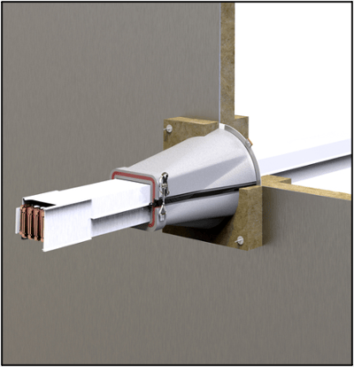
MBD100 Marine Busbar Device: The New A-Class Transit for Schneider Canalis Busbar Assemblies
Busbar systems are often used on board big cruise ships to distribute electrical power to public  spaces or cabin areas. These systems can carry a considerable amount of electricity while taking up less space than comparable power cable systems, making them ideal for high current applications on large projects.
Until now, older wet-applied sealant systems have been used to seal busbars where they penetrated A-Class fire-rated divisions. However, the recent increase in use of busbar systems has generated demand for a better solution. One that could save shipbuilders time and money, while also eliminating hot work.
STI Marine Firestop was invited by a large European shipyard to discuss potential penetration solutions for their Schneider Electric Canalis Busbar System. With the shipyard’s performance criteria in mind, STI Marine Firestop’s Product Development department got to work designing the MBD100 Marine Busbar Device.
STI Marine Firestop’s goal is always the same, to make life easier for the end user. For this reason, the new MBD100 is designed to:
- Offer one solution for both steel bulkheads and decks
- Utilize mechanical fixing in lieu of hot work (tack weld optional)
- Offer a system for A-0 steel divisions without insulation
- Accommodate tolerances in busbar positioning
- Be vibration resistant
- Eliminate the need for wet-applied sealants
- Provide a lightweight solution
The MBD100 is currently tested and approved for use with Schneider Electric’s Canalis KSA Busbar System (500 to 1000 A rating). As the marine industry continues to expand its usage of such busbar systems, we at STI Marine Firestop are working toward enhancing our approvals so that they may be used with a wider variety of Schneider Electric busbar types.
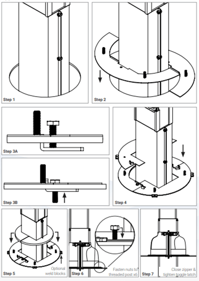
Installation of the MBD100 is simple, and does not require comprehensive training. See below for the installation instructions:
- Cut the opening and secure the busbar in place, nominally centered.
- Position the base plates around the busbar, over the division.
- Tighten the bolts to secure the base plate clamps to the division.
- Position the cover plates over the base plates, inserting the threaded studs through the holes in the cover plates. (Optional – Secure the cover plate to the division via tack welds at each of the four weld blocks.)
- Position the intumescent pad around the busbar, over the cover plates.
- Position the boot around the busbar, inserting threaded studs through the holes toward bottom of the boot, and secure using hardware provided.
- Close the zipper and fasten the toggle latch on the top of the boot.

Please feel free to visit our website for additional information, data sheets, type approval certificates, installation videos, and more!


